
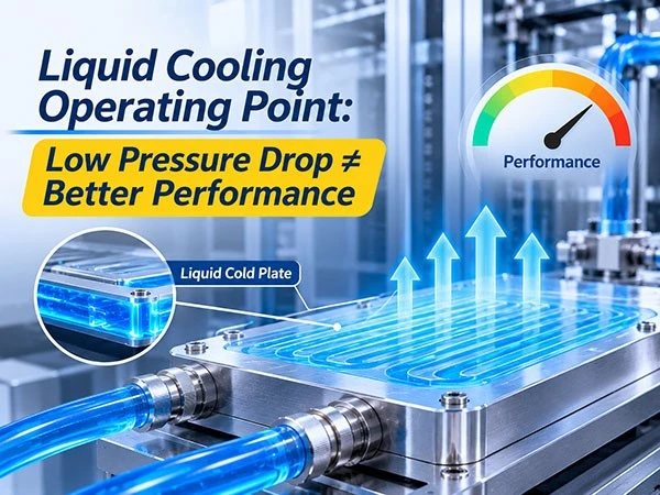
In liquid cooling systems for GPUs and AI servers, the pressure drop across a cold plate is a critical design parameter; however, a lower pressure drop does not necessarily translate to better overall cooling performance for the system.
This is because a cold plate does not operate in isolation. The coolant must circulate through various components, including pumps, piping, connectors, filters, valves, and heat exchangers. The actual flow rate is determined by the interplay between the total system resistance and the performance of the pump.
I. What is the operating point of a liquid cooling system?
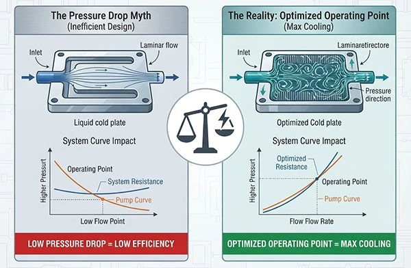
The operating point of a liquid cooling system is defined as the intersection of the pump performance curve and the system resistance curve.
The pump provides the pressure required to drive the flow of the coolant, while various components within the system generate specific pressure drops (resistance).
When the pressure supplied by the pump balances the pressure required by the system, the system operates at a specific flow rate and pressure.
Therefore, the pressure drop specified for a cold plate represents only a portion of the total liquid cooling system and cannot be used in isolation to determine the actual operating flow rate.
II. Why does a lower cold plate pressure drop not necessarily equate to better heat dissipation?
A lower pressure drop across a cold plate indicates that the coolant encounters less flow resistance as it passes through.
In systems using centrifugal pumps-where pump speed often remains constant-reducing system resistance typically shifts the operating point toward a higher flow rate. However, the actual flow rate also depends on the pump's performance curve and the resistance contributed by other system components.
Furthermore, changes in flow rate directly affect the heat transfer performance of the cold plate.
• Excessively high pressure drop: May cause the actual system flow rate to fall below design requirements, thereby impairing the cold plate's heat transfer capacity.
• Excessively low pressure drop: While beneficial for reducing flow resistance, it is still necessary to verify that the cold plate meets the required heat transfer specifications.
• Increased flow rate: Generally helps enhance heat transfer; however, the marginal gains in heat transfer may diminish, while the energy consumption required for pumping may increase.
Consequently, cold plate design should not focus solely on achieving a low pressure drop; rather, it must balance heat transfer capacity, target flow rate, and the pumping capabilities of the system.
III. How is the actual operating point of a liquid cooling system determined?
Engineering design typically involves the following steps:
1. Calculate the total system pressure drop. Determine the pressure loss for each component-such as cold plates, hoses, fittings, filters, valves, heat exchangers, and manifolds-at the target flow rate. Pressure drops for components in series are additive, while parallel branches must be analyzed individually.
2. Establish the system resistance curve. Define the relationship between flow rate and system pressure drop based on the pressure losses at various flow rates. In typical scenarios dominated by turbulent flow and frictional resistance, the pressure drop is generally approximately proportional to the square of the flow rate. 3. Incorporate pump performance curves. Use the performance curve of the actual pump within the CDU (Coolant Distribution Unit) and compare it against the system resistance curve.
4. Determine the system operating point. The intersection of these two curves represents the actual flow rate and pressure at which the pump operates under the given system conditions.
If the system utilizes a variable-frequency pump, pump performance curves for various rotational speeds must also be considered. For systems with multiple parallel branches, the flow distribution across these branches should be evaluated individually.
IV. Why is it necessary to include a pressure drop margin?
During long-term operation of a liquid cooling system, filters may gradually accumulate particulate matter, leading to an increase in their internal pressure drop.
Furthermore, changes in valve status, as well as variations in coolant temperature and viscosity, can affect system resistance and the actual operating point.
Therefore, the design process should not be limited to the operating conditions of a new system with clean filters; it must also account for the pressure loss that occurs when filters reach the point requiring maintenance, along with other potential operational shifts.
The specific pressure drop margin to be reserved should be determined based on the pump's performance curve, the target flow rate, the allowable pressure drop for the filters, and the maintenance cycle-rather than by applying a fixed percentage.
V. Frequently Asked Questions
1. Is a lower pressure drop across the cold plate always better?
Not necessarily. While a lower pressure drop helps reduce system resistance, one must also verify that the cold plate can meet the target heat transfer requirements and that the overall system can provide an adequate flow rate.
2. Why is the pump's maximum flow rate not equal to the actual system flow rate?
A pump's maximum flow rate typically corresponds to operating conditions with minimal resistance. Once integrated into a complete liquid cooling loop, components such as tubing, fittings, filters, valves, and heat exchangers introduce pressure losses; the actual flow rate is determined by the intersection of the pump curve and the system resistance curve.
3. Why is it necessary to calculate the pressure drop for the entire system?
Because the cold plate is only one source of pressure loss. Components such as hoses, connectors, filters, valves, and heat exchangers all influence the actual flow rate of the system.
4. Does increasing the coolant flow rate always improve heat dissipation?
Increasing the flow rate generally helps enhance heat transfer within the cold plate, but the degree of improvement depends on the cold plate's internal structure and specific operating conditions. Furthermore, factors such as pressure drop, pumping power consumption, and system operational constraints must also be considered.
Conclusion
The heat dissipation performance of a liquid cooling system depends not only on the cold plate itself but also on the flow conditions established by the pump, tubing, and other system components.
By analyzing the pump performance curve alongside the system resistance curve, engineers can determine the actual operating point and assess whether the system flow rate meets the cold plate's heat dissipation requirements.
When selecting a liquid cold plate, one should not focus solely on the pressure drop value; instead, the choice should be based on the operating point of the entire liquid cooling system, taking into account heat transfer performance, pressure loss, and long-term operational requirements.